- 您现在的位置:买卖IC网 > Sheet目录321 > DM163035 (Microchip Technology)KIT DEVELOPMENT PICDEM LAB
�� �
�
�PICDEM� TM� Lab� Development� Board� User’s� Guide�
�4.2.4�
�4.2.4.1�
�Lab� 1:� Simple� Compare�
�NEW� REGISTERS� USED� IN� THIS� LAB�
�To� configure� the� peripherals� used� in� this� lab,� the� following� registers� are� used:�
�1.� Comparator� C1� Control� Register� 0:� CM1CON0� (Register� 8-1� in� Section� 8� of� the�
�PIC16F690� Data� Sheet)�
�-� Enables� Comparator� C1.�
�-� Configures� Comparator� output� polarity.�
�-� Enables� the� Comparator� result� to� be� available� internal� only� or� on� the� C1OUT�
�pin� (pin� 17).�
�-� Select� inverting� and� non-inverting� Comparator� 1� reference� input� sources.�
�4.2.4.2�
�OVERVIEW�
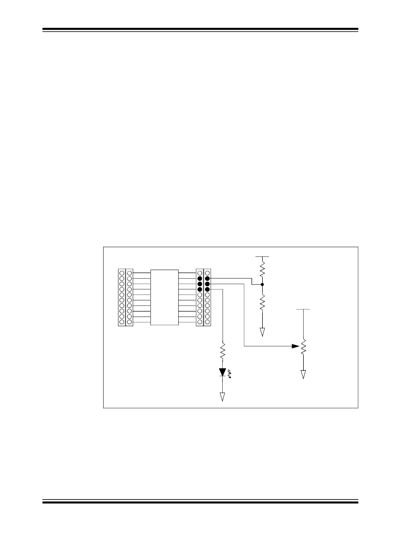
�In� this� lab,� Comparator� 1� on� the� PIC16F690� is� configured� to� perform� a� simple� compare.�
�A� potentiometer� connected� to� the� inverting� input� (C12IN0-)� of� the� comparator� will� be�
�compared� against� the� 2.5V� connected� to� the� non-inverting� input� (C1IN+)� from� a� simple�
�voltage� divider� circuit.� An� LED� connected� to� the� output� of� Comparator� 1� (C1OUT)� will�
�light� or� turn� off� as� follows:�
�?� inverting� reference� >� non-inverting� reference� =� C1OUT� is� low� =� LED� OFF�
�?� inverting� reference� <� non-inverting� reference� =� C1OUT� is� high� =� LED� ON�
��FIGURE� 4-1:�
�SCHEMATIC� FOR� COMPARATOR� LAB� 1�
�V� DD�
�J� 8�
�1�
�2�
�3�
�4�
�5�
�6�
�U2�
�C1IN+�
�C12IN0-�
�C1OUT�
�20�
�19�
�18�
�17�
�16�
�15�
�J9�
�R1�
�10K� ?�
�R2�
�7�
�8�
�9�
�10�
�14�
�13�
�12�
�11�
�10K� ?�
�V� DD�
�V� SS�
�R3�
�DS41369A-page� 62�
�R4�
�470� ?�
�LED1�
�V� SS�
��100K� ?�
�V� SS�
�?� 2009� Microchip� Technology� Inc.�
�发布紧急采购,3分钟左右您将得到回复。
相关PDF资料
DM164120-1
BOARD DEMO PICKIT 2 LP COUNT
DM164120-3
BOARD DEMO PICKIT2 28-PIN
DM164120-5
BOARD DEMO PICKIT 2 64/80-PIN
DM164123
KIT MANAGEMENT SYSTEM PICDEM
DM180021
KIT STARTER MPLAB FOR PIC18F MCU
DM183022
BOARD DEMO PIC18FXX22 64/80TQFP
DM183032
BOARD EXPLORER PICDEM PIC18
DM240001
BOARD DEMO PIC24/DSPIC33/PIC32
相关代理商/技术参数
DM163035+TEFLCST3
制造商:Microchip Technology Inc 功能描述:KIT PICDEMLAB+FLOWCODE-HOME BUNDLE/ 制造商:Microchip Technology Inc 功能描述:PICDEM, FLOW CODE, LAB, DEV KIT
DM163045
功能描述:开发板和工具包 - PIC / DSPIC PICDEM Lab Dev Kit (with PICkit 3) RoHS:否 制造商:Microchip Technology 产品:Starter Kits 工具用于评估:chipKIT 核心:Uno32 接口类型: 工作电源电压:
DM1-63-C
功能描述:端子 Metric Fem Disc non-insulated
RoHS:否 制造商:AVX 产品:Junction Box - Wire to Wire 系列:9826 线规:26-18 接线柱/接头大小: 绝缘: 颜色:Red 型式:Female 触点电镀:Tin over Nickel 触点材料:Beryllium Copper, Phosphor Bronze 端接类型:Crimp
DM1-63M-C
功能描述:端子 Metric Male Disc non-insulated, 0
RoHS:否 制造商:AVX 产品:Junction Box - Wire to Wire 系列:9826 线规:26-18 接线柱/接头大小: 绝缘: 颜色:Red 型式:Female 触点电镀:Tin over Nickel 触点材料:Beryllium Copper, Phosphor Bronze 端接类型:Crimp
DM164
制造商:SITI 制造商全称:SITI 功能描述:8x3-CHANNEL CONSTANT CURRENT LED DRIVER
DM1640
制造商:SANYO 制造商全称:Sanyo Semicon Device 功能描述:16 characters x 4 line Liquid Crystal Dot Matrix Display Module
DM1640-0AL1
制造商:未知厂家 制造商全称:未知厂家 功能描述:Optoelectronic
DM1640-0BL1
制造商:未知厂家 制造商全称:未知厂家 功能描述:Optoelectronic